
Tuesday, January 3, 2012
Back! but moved
I am still working on this project! new progress will be posted here http://www.mr-charisma.com/index.php
Sunday, October 24, 2010
Elevation/Rotation
Back again,
This is the system I have come up with to rotate and elevate the gun. Once I have received the motors from www.robotmarketplace.com I will post a video of it doing its thing.
It's a fairly simple setup really, a motor for each axis rotating a shaft via chain... The whole system can be removed from the tank with 1 split pin for easy maintenance. As a stand alone system it can provide 45 degrees of depression, 45 degrees of elevation and 360 degrees of rotation. Mounted in the tank that movement is limited to 30 degrees of rotation 5 degrees depression and 15 degrees elevation.
Here it is, the tripod gets bolted to the tank floor, the shafts ride on 1/2"bronze bushings. The motors are mounted in the circular cut outs to the side and rear.

Negative elevation! almost looks like it's autonomous...

Mounted in the hull.

=Mr.TigerAce=
Mantle
Hi all, 


Here is the gun mantle. 2mm steel sides, 3mm steel tube, 8mm steel back. It will get the same filler treatment as the superstructure as well as scale welds.

Rear showing the pivot points.

Test fit in the superstructure.

=Mr.TigerAce=
Saturday, October 23, 2010
Back To Building
Its been a while but I'm finally back working on the StuG!
Box of parts I picked up from the laser cutter! The majority of the parts are 2mm mild steel, the airvent cover plate and the splash guards on either side of the gun mantle are 5mm mild steel and the rear of the gun mantle itself is 8mm plate steel! heavy little sucker
For the welding I'm using a WIA 175 gasless mig (courtesy of SignStyle). I run it on a medium setting 80 or so amps with a .9 flux core wire. At 80amps you don't have time to dose off as you'll burn through, I find it easiest to make very fast small welds, 10-15mm long at a time.

The is the superstructure tacked together. You have to be very careful to tack everything perfectly square, if your out of square its a simple matter of breaking the tack and re aligning.

A spare piece of 1.6mm steel sheet comes in very handy as a work bench, you can earth the sheet and anything you place on it can be welded without the need to ground each part. It also allows you to use magnets to hold things in position, as well as allowing you to tack the parts to the bench to hold them in place. Time saver all round.
Here is the rear engine deck, the hatches sit on a small lip that runs the perimeter of each hole.

Hatches in place to check the fit (perfect)

The inside of the superstructure after final welding. There is no need to seem weld the entire part, a few small stitches is more then enough to hold it together. It also generates less heat so the parts don't warp.

Exterior shot. All the welds are done on inside so the outside is perfectly flat and smooth, no grinding required. A small amount of filler will be added to all the seems then sanded flush before painting.

Front view showing the 5mm plate on the mantle opening.

Another view

Sitting on the chassis making sure it fits

Which it does!

I also added these towing eyes, they are fully functional.

Next up will be the gun mantle. Followed (hopefully!) by the fenders.
Stay tuned!
=Mr.TigerAce=
Monday, October 18, 2010
Get your 2H!
Over the past few years my 2H has turned into a G5 and my drafting table has been turned into a 24" lcd, computers are forever getting better and the old pencil is still an old pencil... The best part is mm perfect parts with less skill required to create them!
Few things to get your head around. Try not to get computer F*^&#D, the ability to zoom to microscopic views tends to make each part over complex. The first few parts I made everything was way to precise and detailed, KISS. Your laser cutter will thank you for it.
The right tools.
MS Paint can create 2D drawings no problems at all, you'll be paying for the time it takes your cutter to redraw it! Make sure you work in a vector based program like, Corel Draw, Adobe illustrator, auto cad etc. Most laser cutters want a single vector path with as fewer nodes as possible, to make a nice clean cut.
It definitely takes time to learn each program, the decision of which to use, and how to use it is up to you. Vector is the key.
Here are some parts I have drawn for the StuG in CorelDraw x4.


A KV-1 I drew, begging to be sent to the laser cutter!

Stay tuned
=Mr.TigerAce=
The Hard Part
Hello!
After 4 long tank free months I am back again to let you know updates are coming!
On the list are, Superstructure, Fenders, Mantle, marker mounts including elevation and rotation systems!
Thank you everybody for the support so far! I have been amazed at the conversations started over this little blog on the interwebs! I have been getting a lot of questions and comments which I hope to address in future posts.
The first update will include detailed instruction in regard to designing, drawing, cutting and finally welding the tanks superstructure. I'm not sure if you have looked at a Stug 3G before but you will notice its a complex part so it has a taken a lot of work to get the drawings together (hence the delay!)
So please stay tuned you wont be disappointed!
Cheers,
=Mr.TigerAce=
Monday, June 14, 2010
Sunday, June 13, 2010
Its Alive!
That's a 100lb truck tyre full of water...
Mmmm factory fresh, still has that new tank smell.

The tracks got a coat of flat black, the wheels got a coat of Dunkelgelb, the rest is still in primer for the time being.

I'm using an RS80D for the speed control, a VG6000 for the radio. Its a very simple set up, took 1/2 a day to install. www.robotmarketplace.com

Ready for testing.

This piece of angle provides a convenient place to lift, stops the top of the hull flexing (due to motor torque) and provides support for the front of the superstructure and gun mount.

Next up, fenders and superstructure
=Mr.TigerAce=
Mmmm factory fresh, still has that new tank smell.
The tracks got a coat of flat black, the wheels got a coat of Dunkelgelb, the rest is still in primer for the time being.

I'm using an RS80D for the speed control, a VG6000 for the radio. Its a very simple set up, took 1/2 a day to install. www.robotmarketplace.com

Ready for testing.

This piece of angle provides a convenient place to lift, stops the top of the hull flexing (due to motor torque) and provides support for the front of the superstructure and gun mount.

Next up, fenders and superstructure
=Mr.TigerAce=
Sunday, May 30, 2010
TRACKS!
I'm back again with another update, the tracks are now on! At this stage it starts to look like a tank!

Close up shot of the tracks, they are made of treadmill belt and polyurethane resin.


Idler wheel, this is by far the hardest thing I've had to make yet. I wanted it to be cast in a single piece which made the mould making process very tricky...


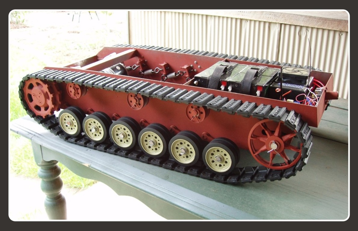
Batteries, 24v 24ah setup. Also visiable is the kill switch at the bottom of the pic.

Very Tank like indeed.

Next up, electronics! Stay tuned, I'll upload a video of it tearing around soon.
=Mr.TigerAce=

Close up shot of the tracks, they are made of treadmill belt and polyurethane resin.


Idler wheel, this is by far the hardest thing I've had to make yet. I wanted it to be cast in a single piece which made the mould making process very tricky...


Batteries, 24v 24ah setup. Also visiable is the kill switch at the bottom of the pic.

Very Tank like indeed.

Some stats on the resin im using.
Comp strength: 4500psi
Tensile strength: 3000psi
Shore Hardness: 70D
Next up, electronics! Stay tuned, I'll upload a video of it tearing around soon.
=Mr.TigerAce=
Wednesday, May 26, 2010

Tuesday, May 25, 2010
WHEELS
I decided to make the wheels look semi accurate in terms of scale, and as I wasn't keen on machining 24 wheels to look good, I decided to cast them in a urethane resin. This means, I only need to make 1 "master" which looks right, then simply make a mould using silicone rubber which captures every detail perfectly. I'll go further into mould making in a later post.
Here is an overall shot of the running gear (minus idlers). All wheels, return rollers, idlers and drive sprockets are cast from "smooth cast 305" its a very rigid urethane resin, casts very nicely, easily tintable. The road wheels, idlers and return rollers all ride on sintered bronze bushings. The drive sprocket is bolted to a flange which is welded to the drive shaft, the bolt heads will be covered in a scale looking "hub".

These are the masters for the road and return wheels. They are just made of styrene, mostly to get the look close, once these are made its easy to cast stronger parts using resins.

Same deal as above, styrene, little bit more complex as the teeth need to be perfect to mesh with the tracks.

The adjustment plate mods I was talking of earlier. Just makes them less likely to flex

Here are the motors installed, tight squeeze, but I guess that's the pay off when its all planned, everything fits! everything is kyed so its all solid as and never gonna slip. Thats very important in a vehicle that constantly changes direction (turning) as the shafts are under huge stress!

Smoth cast, www.smoothon.com
chains, kyed shafts www.surpluscenter.com
Next tracks! as promised.
=Mr.TigerAce=
Here is an overall shot of the running gear (minus idlers). All wheels, return rollers, idlers and drive sprockets are cast from "smooth cast 305" its a very rigid urethane resin, casts very nicely, easily tintable. The road wheels, idlers and return rollers all ride on sintered bronze bushings. The drive sprocket is bolted to a flange which is welded to the drive shaft, the bolt heads will be covered in a scale looking "hub".

These are the masters for the road and return wheels. They are just made of styrene, mostly to get the look close, once these are made its easy to cast stronger parts using resins.

Same deal as above, styrene, little bit more complex as the teeth need to be perfect to mesh with the tracks.

The adjustment plate mods I was talking of earlier. Just makes them less likely to flex
Here are the motors installed, tight squeeze, but I guess that's the pay off when its all planned, everything fits! everything is kyed so its all solid as and never gonna slip. Thats very important in a vehicle that constantly changes direction (turning) as the shafts are under huge stress!

Smoth cast, www.smoothon.com
chains, kyed shafts www.surpluscenter.com
Next tracks! as promised.
=Mr.TigerAce=
Sunday, May 23, 2010
THE HULL
As the hull was lasercut it went together beautifully, it's very important to make sure everything is square whilst assembling so that the swing arm shafts and drive sprocket shafts run true to each other, no one wants a crab walking tank.... Also because the entire thing is 2mm steel, it was easily welded together in a matter of hours with a gasless mig welder.
You must make sure to "tack" weld it all together first to check for square, then only do very small seem welds, as you don't want to introduce to much heat into the steel as it will warp. It's best to take your time and do it properly once.
here is a pic of the assembled lower hull with road wheel swing arms, idler shaft and return roller shafts installed.

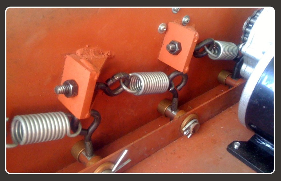
This is the suspension setup. I used eyebolts so I can adjust spring tension and ride height, the shafts ride on sintered bronze bushings. A simple "cotter" pin holds the shafts in place (temporarily fitted) as they see virtually no "pull" load at all. note, I have since added supports to the adjustment plates as they were flexing under load.

This bulkhead removes a lot of the "flex" from the hull, its also there to hold cooling fans, as well as provide support for the battery mount.

Here are the drive shaft bearings (acquired from, http://www.surpluscenter.com/), located in the front of the hull. Notice this area is reinforced with 5mm steel plate as it has to handle a decent amount of force. The drive shaft are 5/8" keyed steel, the swing arm, road wheel and return roller shafts are 1/2" bright steel and the idler shaft is 5/8"

All eyebolts, springs and bushings were purchased from www.mcmaster.com
Stay tuned, next up wheels and tracks!
=Mr.TigerAce=
You must make sure to "tack" weld it all together first to check for square, then only do very small seem welds, as you don't want to introduce to much heat into the steel as it will warp. It's best to take your time and do it properly once.
here is a pic of the assembled lower hull with road wheel swing arms, idler shaft and return roller shafts installed.

This is the suspension setup. I used eyebolts so I can adjust spring tension and ride height, the shafts ride on sintered bronze bushings. A simple "cotter" pin holds the shafts in place (temporarily fitted) as they see virtually no "pull" load at all. note, I have since added supports to the adjustment plates as they were flexing under load.

This bulkhead removes a lot of the "flex" from the hull, its also there to hold cooling fans, as well as provide support for the battery mount.

Here are the drive shaft bearings (acquired from, http://www.surpluscenter.com/), located in the front of the hull. Notice this area is reinforced with 5mm steel plate as it has to handle a decent amount of force. The drive shaft are 5/8" keyed steel, the swing arm, road wheel and return roller shafts are 1/2" bright steel and the idler shaft is 5/8"

All eyebolts, springs and bushings were purchased from www.mcmaster.com
Stay tuned, next up wheels and tracks!
=Mr.TigerAce=
DESIGN
Designing an RC tank is not an exact science, a few factors to take into account.
- The scale detail, do you want your tank to look like a replica, or are you happy with reduced detail to speed up construction?
- The performance, race tank? scale speeds? run time? these are all decisions that need to be made before you start designing
- Materials, wood, steel, aluminium? this is usually determined by the workshop facilities you have access to.
Once you know what you want your tank to do, you can start designing. For me this is my favorite process. I use a basic drawing program (coreldraw x4) which lets me get the basic dimensions down in vector format, which also enables me to send plans to laser cutters and other cad type machines.
For this tank I have decided to go all steel and composite materials. Reason being, steel is easy to work with, you can cut, shape, weld and manipulate it relatively easily. Steel also allows the most internal space as you can use thin sheet metal with a limited amount of reinforcement.
I have also decided to get the entire hull lasercut, this ensures a perfect fit with minimal effort required for final Assembly. The biggest con being, the entire tank needs to be designed from top to bottom before sending off your drawings to the cutter, this can take literally hundreds of hours. Worth it in the end though.
Once I had established the hull material its time to look at motors. I want this tank to have about 350-400 RPM at the drive wheel, this gives me roughly 8.5 - 9.5 km/h. As its made of steel, its going to be heavy so I need some beefy drive motors. I came across these (http://www.monsterscooterparts.com/24v-350w-motor-dirt-quad.html) which look perfect for my application. Reasonable price too.
I now know, I need a 24v battery setup, I've chosen to use 4, 12v 12ah sla batteries, this gives me 24v at 24ah which should give me 45-60min run times.
At this stage its also wise to pick any other components you may need to use, speed controllers, RC transmitters, elevate and rotate setup to name a few. (browse through, http://www.robotmarketplace.com/ to find suitable parts)
Setting a speed of 8-9 km/h means this tank is going to be relatively fast, in harsh conditions a tank of this speed with no suspension will tear itself to pieces. So I'm going for a complete suspension setup, each road wheel is independently sprung, this gives a nice smooth ride to protect the delicate electronics, not to mention it looks sweet! (springs and other misc parts can be found here, http://www.mcmaster.com/)
For the tracks I'm going with a "TTS" (Tyng track system) which is basically a belt with "cleats" attached to both sides to form the track. As the tank is suspended, I need to use a sprocket driven track to allow road wheel movement, a friction track can not handle such movement. This system is good because its light, cheap and performs really well. Cons being, labour intensive to build.
More to follow...
=Mr.TigerAce=
STEP ONE; SELECTION
There are a number of factors that have helped me decide which tank to build, first and foremost is looks.
I tend to stick to German tanks simply for looks alone, the vast majority have a menacing look about them.
The second factor for me is size, I like the smaller style tanks because they are cheaper to build, easier to handle and most importantly, harder to hit with paintballs!
The third and final factor is, whether or not I want a functional turret. I tend to say no to this and end up with assault guns, or tank destroyers.
So for my latest build I'm going with a Sturmgeschutz 3 Ausf G, in a 1943 "kursk" style setup.

Once I have selected the vehicle I want to model, I buy a 1/35th plastic kit of it and use that, along with reference photos to get scale measurements.
1/35th models www.dragonusaonline.com
reference pics and info www.wwiivehicles.com
=Mr.TigerAce=
Welcome!
Hi all, welcome to my blog! Basically I set this up to document the processes involved with building 1/6th scale RC Tanks and equipment, specifically designed to participate in scale battles. At 1/6th a typical tank is around 1400mm long.
The idea is, two or more tanks are pitted against each other on a battlefield, each trying to destroy the enemy. The tanks fire paintballs so its a simple matter of hitting the enemy with a predetermined number of rounds, well in theory...
This raises a few very interesting design challenges, some of which I will try to document shortly.
=Mr.TigerAce=
Subscribe to:
Posts (Atom)
